
1. Which Venstar models does this cover?
Venstar publishes an owner’s manual and installation guide for each thermostat. This article is built from six Venstar documents, downloaded from files.venstar.com and read on 14 November 2026:
- ColorTouch Quick Start & Setup Guide (P/N 88-1094 Rev. 1)
- T7850 Owner’s Manual & Installation Guide (P/N 88-1087 Rev. 1)
- T7900 Owner’s Manual & Installation Guide (P/N 88-1088 Rev. 1, “with Humidity Control”)
- Explorer T3700 manual (P/N 88-1017 Rev. 4b) and Explorer T3900 manual (P/N 88-1015 Rev. 4e)
- Explorer residential spec sheet (88-1082), for the T3800
| Model | Line | Stages (per Venstar) | Backplate terminals |
|---|---|---|---|
| T7850, T7900 | ColorTouch, touchscreen, built-in Wi-Fi | Up to 2 cool and 4 heat stages (installation settings), 1 or 2 compressors on a heat pump | R, C, G, Y1, Y2, W1/O/B, W2, W3/AUX, SENSOR |
| T3700 | Explorer, buttons | 2 heat, 1 cool | R, C, G, Y1, W1/O/B, W2, OUTDOOR SENSOR, DRY CONTACT |
| T3800 | Explorer | Up to 4 heat and 2 cool | See the T3800 manual |
| T3900 | Explorer, adds dual fuel and humidity control | Up to 4 heat and 2 cool | R, C, G, Y1, Y2, W1/O/B, W2, W3, HUM, DEHUM, AUX, OUTDOOR and REMOTE SENSOR, DRY CONTACT |
The ColorTouch quick start guide says the Wi-Fi steps apply to the T7850, T7900, T8850 and T8900, which work on 2.4 GHz Wi-Fi. The Explorer spec sheet lists Wi-Fi as an optional wireless module that is not included with the thermostat. Venstar also sells commercial models (such as the T4700 to T4900 Explorer and T8850/T8900 ColorTouch) and older residential lines; their guides can differ, so check yours.
What these thermostats are not for: the quick start guide warns that if you see large thick wires, wire nuts, or a system labelled 120 V or 240 V, you should not proceed, because the thermostat is not compatible. That is line voltage heat; see our line voltage thermostat guide.
2. What do the Venstar terminals mean?
This table combines the backplate tables in the T7900, T3700 and T3900 guides.
| Terminal | What Venstar says it is | Note |
|---|---|---|
| R | 24 VAC return | The only R terminal. The wire chart sends Rh, R, M, Vr or A from the old thermostat here. |
| C | 24 VAC common | Required on every model covered here. |
| G | Fan relay | Old G or F goes here. |
| Y1, Y2 | 1st and 2nd stage compressor relay | Y2 is not on the T3700. |
| W1/O/B | 1st stage heat circuit, or the reversing valve on a heat pump | Old W1, W or O/B goes here (O/B only for a heat pump). |
| W2 | 2nd stage heat circuit | Aux heat on a heat pump with one compressor stage. |
| W3 (W3/AUX on the ColorTouch) | 3rd stage heat circuit | On the ColorTouch the AUX Output setting can turn it into a humidifier or dehumidifier output. |
| HUM, DEHUM, AUX | Humidifier and dehumidifier control circuits, aux output | T3900 only. |
| SENSOR terminals | Remote, outdoor, supply or return sensor | Old OUT+ and OUT- go here. Not for system wires. |
| DRY CONTACT | Dry contact input | Explorer only, for an accessory such as a time clock or door switch. |
The detail that trips people up is W1/O/B. On most other brands, W1 and O/B are separate terminals. On these Venstar models they are the same screw, and the GAS/EL or HP DIP switch decides what it does. That is why, on a heat pump, auxiliary heat moves to W2 instead of W1. For the meaning of each letter across brands, see our terminal letter index.
3. How do you wire a Venstar thermostat to a furnace and air conditioner?
These rows follow the conventional sample wiring diagrams in the T7900 and T3900 guides. The GAS/EL or HP switch stays on GAS/EL for all of them.
| System | Wires and terminals | GAS or ELEC switch |
|---|---|---|
| Heat only, 3 wires | R, C, W1/O/B (heat) | As your heat type |
| Cool only, 4 wires | R, C, Y1 (cool), G (fan) | Any |
| Gas furnace and AC, 5 wires | R, C, W1/O/B (heat), Y1 (cool), G (fan) | GAS |
| Electric furnace or air handler and AC, 5 wires | R, C, W1/O/B (heat), Y1 (cool), G (fan) | ELEC |
| 2 stage cooling, 3 stage heat, 8 wires | R, C, W1/O/B, W2, W3 (or W3/AUX), Y1, Y2, G | As your heat type |
The GAS or ELEC switch matters on a conventional system because it decides who runs the blower in heating. Venstar’s explanation: with GAS, the thermostat does not energize G in heating (a gas furnace runs its own blower); with ELEC, the thermostat energizes the fan in heating. If the fan does not come on with an electric furnace, this switch is the first thing to check.
What about a 2 wire heat only system?
A plain boiler or furnace with only R and W at the thermostat does not have the C wire Venstar needs. The ColorTouch quick start and T7900 guide say that in this case the Add-A-Wire accessory will not work and you need to install another wire for C. The T7900 guide’s 2 wire diagram, on the other hand, says to pull new wire or buy the ACC0410 two-wire kit. Because the two statements disagree, running new cable is the option both pages support; our wire gauge and new wire guide covers that, and the 2-wire heat only page lists thermostats that work without C.
What if the old thermostat had separate Rh and Rc wires?
The ColorTouch and Explorer backplates have a single R terminal, and the guides’ wire chart lists Rh and R (plus M, Vr and A) as going to it. None of the sample diagrams show a system with two transformers. If you have two R wires with no jumper between them on the old thermostat, the Venstar guides do not cover it, so do not twist them together; see our dual transformer page and ask Venstar or a technician first.
4. How do you wire a Venstar thermostat to a heat pump?
Set the GAS/EL or HP switch to HP first. The heat pump diagrams in the T7900 and T3900 guides then use these terminals:
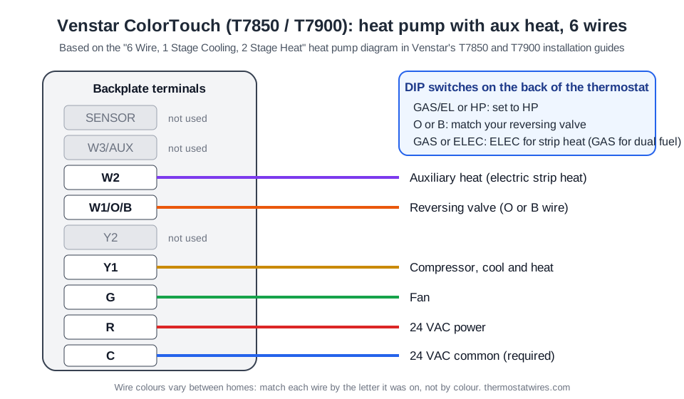
| Terminal | Heat pump, no aux heat (5 wires) | Heat pump with aux heat (6 wires) | 2 compressor stages (7 wires) | 2 compressor stages + 2 aux (8 wires) |
|---|---|---|---|---|
| R | 24 VAC power | 24 VAC power | 24 VAC power | 24 VAC power |
| C | 24 VAC common | 24 VAC common | 24 VAC common | 24 VAC common |
| W1/O/B | Reversing valve | Reversing valve | Reversing valve | Reversing valve |
| Y1 | Compressor (cool or heat) | Compressor | 1st stage compressor | 1st stage compressor |
| Y2 | Not used | Not used | 2nd stage compressor | 2nd stage compressor |
| W2 | Not used | Aux heat | 3rd stage heat (aux) | 3rd stage heat (aux) |
| W3 | Not used | Not used | Not used | 4th stage heat (aux) |
| G | Fan | Fan | Fan | Fan |
For the 7 and 8 wire layouts, the guides add that the Number of Compressor Stages setting must be set to 2. The Explorer guide also notes that when the T3900 runs a 4th stage of heat, the display still shows 3rd stage.
O or B: how do you pick?
There is no separate O and B screw. Your old thermostat’s O/B wire goes on W1/O/B, and the O or B DIP switch decides when it is powered: O energizes W1/O/B in cooling, B energizes it in heating. Use the same letter your old thermostat used. Watch for a B wire that is really a common wire on some older systems; our O/B page and B terminal page explain how to tell.
Where does emergency heat go?
Neither line has an E terminal. Both guides describe Emergency Heat as a mode, available only when the thermostat is set for a heat pump, that runs the fan and the auxiliary heat stages on a call for heat and makes the heat pump compressor and all cooling unavailable. So emergency heat uses the same W2 (and W3) aux wires. If your old thermostat had separate E and AUX wires going to different relays, the Venstar guides do not show that setup; ask a technician. For the difference between the two, see aux heat vs emergency heat.
How do you wire dual fuel?
The T7900 guide’s dual fuel diagram (heat pump with a gas, oil or propane furnace) uses R, C, W1/O/B for the reversing valve, W2 to the furnace as 3rd stage heat, Y1 and Y2 for two compressor stages and G for the fan, with HP and GAS on the switches and Dual Fuel set to On. The guide says Dual Fuel only appears in the settings when the switches are on HP and GAS. With the Changeover With Outdoor setting on, the switch to the furnace happens at an outdoor temperature you pick (the balance point, 0 to 60 degrees F, read from an outdoor sensor); with it off, a third stage heat demand triggers the switch. Our heat pump thermostat wiring guide covers dual fuel in general.
5. Does a Venstar thermostat need a C wire?
Yes. The T7850, T7900, T3700 and T3900 guides each state that the thermostat requires both R (24 VAC return) and C (24 VAC common) to be connected. There is no battery-only mode for these models. If C is missing, the troubleshooting tables point to a blank display and tell you to check for 24 VAC between R and C.
When you are one wire short, the guides give three options: use the wires you have and give up independent fan control, pull new thermostat wire, or install a Venstar Add-A-Wire accessory (ACC-0410 in the quick start guide).
How does Venstar’s 4-wires-for-5 method work?
For a single stage gas or oil furnace with air conditioning, the guides’ method uses a 3 inch piece of thermostat wire as a jumper at the furnace end:
- Turn the power off.
- At the furnace control board, remove the G wire from the G terminal and put it on C.
- Jumper G to Y on the board (Y will now hold more than one wire).
- At the thermostat, connect the wire that used to be on G to C. Every other wire goes to the same letter at both ends.
The trade-off, in Venstar’s words, is that the fan only runs with a heating or cooling demand. The guides say this method is not an option for an all-electric heat system with air conditioning. The same idea applies to a 6 wire system with only 5 wires. Our no C wire guide compares this with adapters and new cable, and the C wire page shows how to find an unused conductor.
6. How do you set the Venstar DIP switches?
The ColorTouch and Explorer guides show three small switches on the back of the thermostat. Set them before you snap the thermostat onto the backplate.
| Switch | Positions | What it does |
|---|---|---|
| GAS/EL or HP | GAS/EL, HP | Conventional system or heat pump. Venstar: if your system is anything other than a heat pump, leave it on GAS/EL. (The T7900 guide notes some commercial heat pumps need GAS/EL; check their literature.) |
| O or B | O, B | Heat pump only. O: W1/O/B energizes in cooling. B: W1/O/B energizes in heating. |
| GAS or ELEC | GAS, ELEC | On GAS/EL: GAS means the thermostat does not energize G in heating, ELEC means it does. On HP: GAS stops aux heat from running during heat pump operation (use it for dual fuel); ELEC allows up to two stages of auxiliary strip heat. |
After the switches, check the installation settings. On the ColorTouch the T7900 guide lists Heat & Cool Stages (factory 1 heat / 1 cool), Compressor Stages (heat pump only), Aux Heat Stages (0 to 2), Cycles Per Hour (default 6), Compressor Min OFF Time (5 minutes by default; none, 1 or 5 minutes), heat pump and aux heat lockout temperatures, Dual Fuel and AUX Output usage. On the Explorer, the technician setup opens when you hold SETUP for 10 seconds, and its first screens show the switch positions, which is a quick way to confirm them.
7. Wiring steps
The guides tell you to call a qualified technician if you are unsure about any step. If you do it yourself:
- Turn off the power to the heating and cooling system at the breaker panel, then confirm the old thermostat no longer starts anything.
- Photograph the old wiring, then tape and label each wire with the letter of the terminal it was on. Go by letters, not colours; our wire colour guide explains why.
- Count your wires against the system type: heat only needs 3, furnace and AC 5, heat pump 5, heat pump with aux 6. If you are short, decide now between new wire, the Add-A-Wire accessory or the 4-wires-for-5 method.
- Mount the backplate. On the ColorTouch, the guide notes that the backplate does not fully cover a vertical junction box; Venstar’s ACC-WPLWH wall plate or a horizontally mounted single-gang box is needed for that.
- Connect the wires using the tables in sections 3 and 4. W1, W and O/B all go on W1/O/B, but only one of them can be used.
- Set the three DIP switches on the back of the thermostat.
- Snap the thermostat onto the backplate. If you feel resistance, the quick start says to stop, check that the pins are straight and no wire is in the way, and try again.
- Restore power and set the stages and other installation settings.
- Test each output. The ColorTouch has a Test Outputs feature in the installation settings and the Explorer has an output test in technician setup, both without the usual time delays.
8. What if it does not work after wiring?
| What you see | Cause Venstar gives, or the rule to check |
|---|---|
| Blank display | No proper power. Check for 24 VAC between R and C at the thermostat. |
| Heat pump heats when you ask for cooling | The O or B switch is in the wrong position. Move it to the other side. |
| Heat and cooling both run on a call for cooling | The GAS/EL or HP switch is on HP but the system is a furnace and air conditioner. Set it to GAS/EL. |
| Air conditioning does not try to start | The compressor minimum off time is holding it off, or the cooling setpoint (or its limit) is too high. |
| Aux heat never runs on a heat pump | The GAS or ELEC switch is on GAS, which blocks aux heat during heat pump operation; set ELEC for electric strip heat. Also check that the aux wire is on W2, not W1/O/B. |
| Fan does not run with electric heat | The GAS or ELEC switch is on GAS on a conventional system. Set it to ELEC. |
| Air handler fuse blows only when the thermostat is pushed onto the backplate | The outdoor sensor or its wiring is shorted. Check the sensor wires. |
To measure the voltage, use our multimeter guide. For faults outside the thermostat, the thermostat troubleshooting guide works through each wire. If you are comparing brands, our Braeburn wiring article shows a thermostat that keeps W1 and O/B on separate terminals and can run on batteries.
9. Frequently asked questions
Does a Venstar thermostat need a C wire?
Yes, for the ColorTouch and Explorer models. The T7850, T7900, T3700 and T3900 installation guides all say the thermostat requires both R (24 VAC return) and C (24 VAC common) connected to the backplate terminals. The ColorTouch quick start guide adds that a heat only system therefore needs 3 wires (R, C and W), not the usual 2.
What does W1/O/B mean on a Venstar thermostat?
It is one terminal with two jobs. With the GAS/EL or HP DIP switch on GAS/EL, W1/O/B is the first stage heat wire. With the switch on HP, the same terminal drives the heat pump reversing valve, energized in cooling when the O or B switch is on O, or in heating when it is on B.
Where does the aux heat wire go on a Venstar ColorTouch?
On W2. Venstar’s heat pump diagram for a 6 wire system with auxiliary heat puts the reversing valve on W1/O/B, the compressor on Y1 and aux heat on W2. With two compressor stages, Y2 takes the second compressor and W2 becomes the third stage of heat.
Where does the E (emergency heat) wire go on a Venstar thermostat?
The ColorTouch and Explorer backplates have no E terminal. In Venstar’s emergency heat mode the thermostat runs the fan and the auxiliary heat stages and locks out the compressor, so emergency heat uses the aux heat wire on W2. If your old thermostat had a separate E wire, the Venstar guides do not show where it goes; ask Venstar support or a technician.
Can I install a Venstar ColorTouch with only 4 wires?
Yes, for a single stage gas or oil furnace with air conditioning, if you accept that the fan only runs during a heating or cooling call. Venstar’s method moves the G wire to C at the furnace and jumpers G to Y there. The guide says this does not work for an all-electric system with air conditioning; use new wire or the Add-A-Wire accessory instead.
Why does my Venstar heat pump heat when I ask for cooling?
The O or B DIP switch is on the wrong side. Venstar’s troubleshooting tables give this cause and tell you to flip the reversing valve switch to the other position. If both heat and cool come on when you call for cooling on a furnace and air conditioner, the GAS/EL or HP switch is on HP and should be on GAS/EL.
How do I set a Venstar thermostat for dual fuel?
Set the GAS/EL or HP switch to HP and the GAS or ELEC switch to GAS, then turn Dual Fuel on in the installation settings. The T7900 guide puts the furnace on W2 as the third stage of heat in its dual fuel diagram and lets you pick a balance point from 0 to 60 degrees F when an outdoor sensor is used.