
1. Which T3 Pro do you have, TH3110U or TH3210U?
The T3 Pro is Honeywell Home’s basic thermostat for contractors, made by Resideo, with a Menu button, Heat On / Cool On indication and a push-in UWP wall plate. One installation guide (Resideo 33-00520EFS-05) covers both versions. The model number is on the box and on the back of the thermostat, and the guide marks every difference with “TH3210U only”:
| Model | Systems shown in the guide | AUX (W2) and E | Em Heat mode |
|---|---|---|---|
| TH3110U2008 | 1 heat / 1 cool furnace and air conditioner (one or two transformers), heat only, heat only with fan, Series 20 valve, power-open zone valve, cool only, 1H/1C heat pump without backup heat | Not used | No |
| TH3210U2004 | Everything above, plus a 2H/1C heat pump: one compressor stage and one auxiliary heat stage | Used | Yes |
If you are still choosing, the rule is simple: buy the TH3210U2004 if you have a heat pump with electric strips or another backup heat source; otherwise the TH3110U2008 does the job. Neither version runs a second compressor stage or a second furnace stage (section 10). The T3 Pro is a 24 volt thermostat. If the old one is fed by thick wires and wire nuts from a baseboard heater, it is a line voltage system and the T3 Pro is not the right part; read our line voltage thermostat guide first.
2. What does each UWP terminal do on the T3 Pro?
The UWP (universal wall plate) is shared by several Honeywell Pro thermostats, so it has more terminals than the T3 Pro uses. This is the guide’s terminal list, with the commonly used ones first:
| Terminal | Function on the T3 Pro | Model |
|---|---|---|
| R | 24 VAC power from the heating transformer | Both |
| Rc | 24 VAC power from the cooling transformer; joined to R by the R slider tab | Both |
| C | 24 VAC common; on two-transformer systems, use the common from the cooling transformer | Both |
| W | Heat, stage 1, on conventional systems; not used on heat pumps | Both |
| Y | Compressor contactor, stage 1 | Both |
| G | Fan | Both |
| O/B | Heat pump changeover (reversing) valve | Both |
| AUX (W2) | Auxiliary heat | TH3210U only |
| E | Emergency heat | TH3210U only |
| S, S, Y2, U, U, L/A, K | Not used for the T3 thermostat | Neither |
Two parts of the plate cause most mistakes. The R slider tab is a built-in jumper between R and Rc. Push it up (the 1 wire position) if there is only one R wire, whether the old thermostat had it on R, Rc or RH. Push it down (2 wires) if one wire was on R and another on Rc, which keeps two transformers apart. The U slider tabs should be left in place on T3 Pro models. Our Rh and Rc page explains how to tell a one-transformer system from a two-transformer one.
The unused terminals matter too. A wire from an old L terminal (a heat pump fault light) has nowhere to go, because L/A is not used on the T3; cap or tape it, and see our L, S and T terminals page for what that light did. A wire on Y2 means your system has a second compressor stage, which the T3 Pro cannot run; our Y and Y2 page explains the difference.
3. Does the T3 Pro need a C wire?
No. The Honeywell T3 Pro ships with 2 AA batteries, and Resideo’s guide says you can insert them “for primary or backup power.” With R and C wired, AC power is primary and the batteries keep the settings and display going if power drops. Without C, the batteries run the thermostat. The guide says the C terminal “is optional if batteries are installed, but it is recommended.”
There is one feature that needs C. Installer setting 1400 Backlighting offers On Demand or Continuous, and the guide notes “Common wire needed for continuous.” On batteries alone, the backlight comes on only when you press a button.
Here the T3 Pro differs from its bigger brother. On the Honeywell T4 Pro, four-wire homes can add a THP9045A C-wire adapter and move the Y or G wire to K. The T3 Pro guide lists K as not used, so that method is not offered for this model. If you want C on a T3 Pro and have only R, W, Y and G at the wall:
- Look for a spare conductor folded back in the wall or at the furnace. Many cables carry more wires than were connected. Our multimeter guide shows how to confirm 24 V between R and a candidate C wire.
- Run new cable. Use 18 to 22 gauge thermostat wire; the guide says shielded cable is not required.
- Or keep the T3 Pro on batteries, which the guide allows. Our no C wire guide compares the other options.
4. How do you wire a T3 Pro to a furnace and air conditioner?
For a gas, oil or electric furnace with central air conditioning, or a boiler, the guide gives these wire sets. Either model works for all of them. A dash means the terminal stays empty.
| System | R | Rc | C | W | Y | G | R slider tab |
|---|---|---|---|---|---|---|---|
| 1 heat / 1 cool, one transformer | Power | - | Optional | Heat | Compressor | Fan | Up |
| 1 heat / 1 cool, two transformers | Heating transformer | Cooling transformer | Optional, from the cooling transformer | Heat | Compressor | Fan | Down |
| Heat only | Power | - | Optional | Heat | - | - | Up |
| Heat only with fan | Power | - | Optional | Heat | - | Fan | Up |
| Cool only | Power | - | Optional | - | Compressor | Fan | Up |
| Power-open zone valve | Power | - | Optional | Valve | - | - | Up |
| Series 20 valve | Valve terminal “R” | - | Optional | Valve terminal “B” | Valve terminal “W” | - | Up |
The Series 20 row is the one to read twice: the valve’s “W” goes to the thermostat’s Y and the valve’s “B” goes to the thermostat’s W. For the Series 20 and power-open zone valve setups, the guide says to set the heat system type to Radiant Heat and the number of cool stages to 0 in installer setup. If your boiler has several zones on a zone controller, our boiler zone valve guide explains which wires belong to the thermostat.
The guide’s electrical ratings table also lists W at 750 mV DC and 100 mA for a Powerpile (millivolt) heating system, but it shows no millivolt wiring diagram. If your heater has a millivolt gas valve with no transformer, confirm the hookup with Resideo before relying on that row.
5. How do you wire a T3 Pro to a heat pump?
The guide has two heat pump tables. Both put power on R (slider up), the compressor on Y, the fan on G and the changeover valve on O/B, with C optional. The difference is backup heat:
| Terminal | 1H/1C heat pump, no backup heat (TH3110U or TH3210U) | 2H/1C heat pump with backup heat (TH3210U only) |
|---|---|---|
| R | Power | Power |
| C | 24 VAC common (optional) | 24 VAC common (optional) |
| Y | Compressor contactor | Compressor contactor |
| G | Fan | Fan |
| O/B | Changeover valve | Changeover valve |
| AUX | - | Auxiliary heat |
| E | - | Emergency heat |
| W | Empty. The guide: “Do not use this terminal for heat pump applications!” | |
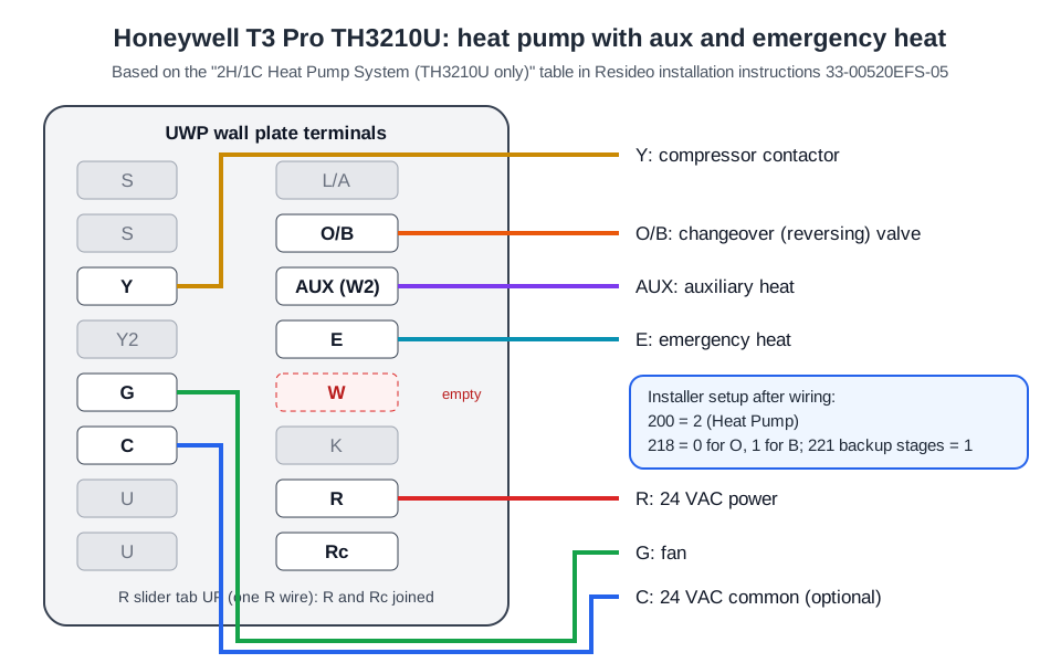
On a heat pump, the backup heat wire from the old thermostat may have been labelled W2, AUX or X2; it goes to AUX on a TH3210U. If the old thermostat had no separate E wire, leave E empty. The TH3110U has no working AUX or E, so it cannot control backup heat at all. Our aux vs emergency heat guide explains the difference, and the heat pump with emergency heat diagram shows the same set on other brands.
Some older heat pump thermostats have separate O and B terminals, each with a wire. Honeywell Home’s How to Wire a Thermostat page says to “tape off the B wire so it doesn’t make contact and connect the O wire to the O/B terminal.” Be careful with B, because it means different things on different equipment: on many Trane, American Standard and Carrier systems a B wire is the 24 V common, which belongs on C, while Rheem and Ruud heat pumps use B as a reversing valve wire energized in heating. Our B wire as common page, Rheem and Ruud B wire page and O/B terminal page show how to tell which you have.
6. Step by step: replacing your old thermostat with a T3 Pro
- Turn off power to the heating and cooling system at the breaker box or the furnace switch. The guide says this before every mounting step.
- Photograph the old wiring and label each wire with the letter of the terminal it was on. Go by the letter, not the colour; our wire colour guide explains why colours cannot be trusted.
- Check for wires the T3 Pro cannot use: Y2, L, a second W for a two-stage furnace, or numbered or letter terminals such as 1 2 3 or A B C (a communicating system). If you find one, stop and read section 10 before going on.
- Mount the UWP. Level it on the wall, mark the holes and drill 7/32 inch holes for red anchors or 3/16 inch for yellow, then tap the anchors in. Pull the door open, feed the wires through the wiring hole and fit 3 screws until the plate no longer moves. Use the optional cover plate if you need to hide paint marks from the old thermostat.
- Insert each wire into the push-in terminal with the matching letter. To release a wire, press the terminal tab.
- Set the R slider tab: up for one R wire, down for separate R and Rc wires. Leave the U tabs where they are.
- Insert the 2 AA batteries, even if you have a C wire, so the thermostat has backup power.
- Push excess wire back into the wall and close the UWP door. It should stay closed without bulging.
- Line the thermostat up with the UWP and push gently until it snaps in place. To remove it later, pull it off the plate.
- Turn the power back on. The thermostat opens installer setup on its first power-up; work through section 8 before you use it, especially on a heat pump.
Not sure which wire is live? Our free thermostat wiring tool takes the letters from your old thermostat and shows the matching connections and warnings.
7. Worked examples from real wire sets
These examples use the guide’s tables to map common old-thermostat wire sets onto a T3 Pro.
| Old thermostat wires | T3 Pro model | Where they go | Settings |
|---|---|---|---|
| R, W, Y, G (no C), gas furnace with AC | TH3110U2008 | R, W, Y, G; slider up; run on batteries | 200 = 1, 205 = 1 or 2 to match the furnace |
| Rh, Rc, W, Y, G, C, boiler and separate AC | TH3110U2008 | Rh to R, Rc to Rc, W, Y, G, C (from the cooling transformer); slider down | 200 = 3, 205 = 9 for hot water radiant heat |
| R, C, Y, G, O, W2, E, heat pump with strips | TH3210U2004 | R, C, Y, G, O to O/B, W2 to AUX, E to E; W empty | 200 = 2, 218 = 0, 220 = 1, 221 backup stages = 1 |
| R, C, Y, G, B, heat pump without strips | Either | R, C, Y, G, B to O/B; W empty | 200 = 2, 218 = 1 |
| R, C, Y, Y2, G, W, two-stage AC | Neither | Y2 has no terminal on the T3 Pro | Choose a two-stage model |
The third row is the most common heat pump case. The O wire energizes the reversing valve in cooling, so 218 is set to 0 (O). In the fourth row, the B wire is a reversing valve wire energized in heating (the Rheem and Ruud style), so 218 is set to 1. If you are unsure whether a B wire is a valve wire or a common, measure first: a common reads about 24 V to R with the system idle.
8. Which installer settings do you need after wiring?
The T3 Pro enters installer setup (ISU) the first time it is powered up. To get back in, press and hold Menu on the home screen for about 5 seconds. Press Edit (-) to change a value and Next (+) to save it and go to the next setup number; when you have been through them all, press Done to save and exit. The settings that depend on your wiring:
| ISU | Setting | Options in the guide |
|---|---|---|
| 200 | Heating System Type | 1 conventional forced air, 2 heat pump, 3 radiant heat, 5 none (cool only) |
| 205 | Heating Equipment Type | 1 standard efficiency gas, 2 high efficiency gas, 3 oil, 4 electric, 5 hot water fan coil, 9 hot water radiant, 12 steam; hidden when 200 is heat pump |
| 218 | Reversing Valve O/B | 0 = O (O/B on in cool), 1 = B (O/B on in heat); heat pumps only |
| 220 | Cool or Compressor Stages | 0 or 1; 0 if you have no cooling |
| 221 | Heat or Backup Heat Stages | Heat stages 1; backup heat stages 0 or 1 |
| 230 | Fan Control in Heat | 1 equipment controls fan, 2 thermostat controls fan; shown only for electric forced air or fan coil |
| 300 | System Changeover | 0 manual, 1 automatic (adds the Auto system mode) |
| 387 | Compressor Protection | 0 off, or a minimum off time of 1 to 5 minutes; “Wait” shows while it counts |
| 1400 | Backlighting | 0 on demand, 1 continuous (needs C) |
The guide also lists 125 (Fahrenheit or Celsius), 303 auto changeover differential (0 to 5 °F), 340 backup heat droop and 350 upstage timer to backup heat (both TH3210U only), cycle rates 365, 370 and 375, setpoint limits 430 and 431, backlight brightness 1401 and a display offset 1420 of up to 3 °F either way. For heating cycle rate 370, the guide recommends 5 cycles per hour for standard efficiency gas or oil, 3 for high efficiency gas, fan coils and hot water radiant, 9 for electric forced air and 1 for steam.
Once setup is done, press Menu and use Mode (+) to pick Auto, Heat, Cool, Em Heat (TH3210U only) or Off, and Fan (-) to pick Auto or On, then Done. The T3 Pro heats from 32 to 90 °F and cools from 50 to 99 °F, according to the guide’s specifications.
9. Why is my T3 Pro not working after wiring?
| Symptom | Likely cause | What to do |
|---|---|---|
| Display is blank | No power, or dead batteries | Check the breaker, the furnace power switch and that the furnace door is closed; fit fresh AA alkaline batteries |
| “Heat On” or “Cool On” flashing | Compressor protection is engaged | Wait 5 minutes; the guide says the system restarts safely after that |
| Heat or cool does not respond | Wrong mode or setpoint, or power off | Set Heat with a setpoint above room temperature (or Cool below it), check the breaker and furnace door, wait 5 minutes |
| Aux heat runs in cooling | A wire on W with a heat pump | Move the backup heat wire to AUX (TH3210U) and leave W empty |
| Cooling runs on a call for heat | A wire on W with a heat pump, or 218 set the wrong way | Check W is empty, then flip 218 between O and B |
| No Em Heat mode | TH3110U model, or 200 not set to heat pump | Em Heat exists only on the TH3210U with 200 = 2 |
| Backlight will not stay on | No C wire | Continuous backlight (1400 = 1) needs a common wire |
The guide also warns that compressor protection is bypassed during testing, so do not cycle the compressor quickly when checking your work. For faults outside these, our thermostat troubleshooting checklist covers fuses and transformers, and Resideo’s customer site lists support contacts (the guide gives Customer Care at 1-800-468-1502).
10. When is the T3 Pro the wrong thermostat?
The T3 Pro is a simple, reliable choice for single-stage systems, but its guide rules it out for several setups. Pick something else if you have:
- Two-stage cooling or a two-stage heat pump (a wire on Y2). Setting 220 allows only 0 or 1 compressor stages. The Honeywell T6 Pro handles more stages on the same kind of wall plate.
- A two-stage furnace (wires on W and W2 with no heat pump). Setting 221 allows 1 heat stage on a conventional system.
- A four-wire system and a smart thermostat in mind. The T3 Pro does not need C, but its guide describes no Wi-Fi or app features, and the K terminal is not used, so you cannot add C with a THP9045A as you can on the T4 Pro.
- A communicating system with terminals such as A B C D or 1 2 3. Honeywell Home’s wiring page warns that a new thermostat may not be directly compatible with those.
- Line voltage heat (120 or 240 V baseboard heaters). The T3 Pro’s terminals are rated 20 to 30 VAC.
For a smart thermostat on the same Honeywell plate, see our Honeywell T10 Pro wiring guide, which requires a C wire.
11. Frequently asked questions
Does the Honeywell T3 Pro need a C wire?
No. Resideo’s T3 Pro installation instructions say the thermostat runs on 2 AA batteries, on a C wire, or on both, and that the C terminal is optional if batteries are installed, though it is recommended. With R and C connected, AC power is primary and the batteries are backup. A C wire is required only if you want the backlight on continuously (installer setting 1400).
What is the difference between the TH3110U2008 and TH3210U2004?
Backup heat. Both use the same UWP wall plate, but only the TH3210U2004 uses the AUX/W2 and E terminals and has an Em Heat mode, so it is the model for a heat pump with auxiliary heat (2 heat, 1 cool). The TH3110U2008 handles one heat and one cool stage: a furnace with air conditioning, a heat-only or cool-only system, or a heat pump with no backup heat.
Where does the W wire go on a T3 Pro with a heat pump?
Nowhere. Both heat pump tables in the T3 Pro guide say “Do not use this terminal for heat pump applications!” next to W. Backup heat goes on AUX and emergency heat on E, and only the TH3210U uses those terminals. A wire left on W is the cause the guide gives when aux heat runs in cooling or cooling runs on a heat call.
How do I set O or B on the Honeywell T3 Pro?
In installer setup, set 200 Heating System Type to 2 (Heat Pump). Option 218 Reversing Valve O/B then appears: 0 means O, energized in cool, and 1 means B, energized in heat. The wire goes on the O/B terminal either way. If the heat pump cools when you ask for heat, 218 is usually set the wrong way.
How do I get into installer setup on a T3 Pro?
The T3 Pro opens installer setup by itself the first time it is powered up. To get back in later, press and hold the Menu button on the home screen for about 5 seconds. Press Edit (-) to change a value, Next (+) to save it and move to the next setup number, and Done to save and exit.
Can the T3 Pro use a Honeywell C-wire adapter (THP9045A)?
Not according to its installation guide. The T3 Pro guide lists the K terminal as “Not used for T3 thermostat,” and K is the terminal the THP9045A wire saver needs on the T4 Pro and other Honeywell Pro models. With four wires and no C, run the T3 Pro on its AA batteries, use a spare conductor if the cable has one, or run new cable.
Can a Honeywell T3 Pro control two-stage cooling or a two-stage furnace?
No. The guide lists Y2 as not used for the T3 thermostat, installer setting 220 allows 0 or 1 cool or compressor stages, and setting 221 allows 1 heat stage on a conventional system. A two-stage air conditioner, a two-stage heat pump or a two-stage furnace needs a thermostat that supports more stages, such as the Honeywell T6 Pro.
What size thermostat wire does the T3 Pro use?
Resideo’s guide says to use 18 to 22 gauge thermostat wire and that shielded cable is not required. Each conductor pushes into its terminal on the UWP, and pressing the terminal tab releases it.